Electronics History: The 555 Timer

The 555 Timer IC (Wikipedia photo)
While researching for my last post about the plasma arc audio speaker, it got me waxing nostalgic about the 555 Timer Integrated Circuit, one of the most versatile ICs ever designed. The Plasma Arc Audio Speaker I wrote about was one of the coolest things I have ever seen built around a 555, which is a favorite and classic chip that first hit the silicon scene in the 1970s.
The first circuit I ever built (somewhere around 1985, when I was ten years old) was a digital counter using a 555 as a square wave generator, feeding a 7490 decade counter, and using a 7447 BCD-to-Decimal IC to run a seven segment LED display. It was based on the circuit in the Forrest Mims book.
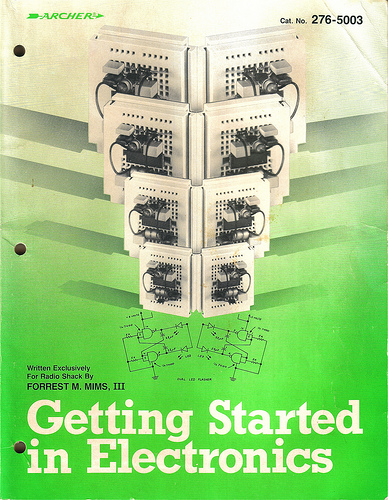
Original print cover of “Getting Started in Electronics” (Radio Shack version)
“Getting Started In Electronics,” a classic that was available at Radio Shack for a few bucks in the 1980s and is still in print-although it costs about $17 now at Amazon. Mr. Mims is still alive and resides here in Texas and I have had the pleasure to speak with him a few times-one could say that there were two authors– Forrest Mims and Gordon West WB6NOA –that helped kindled my interest in amateur radio and electronics and shape the beginnings of my career.
Morse Code oscillator built around a 555 Timer IC (from electronics-project-design.com)
Another of my favorite projects from my childhood — a tone oscillator made from a 555 (similar circuit at left) — was the basis of a Morse Code practice oscillator I built in 1989 while practicing for my Novice amateur radio license. While I don’t have the exact schematic I used way back then, Electronics Project Design has published a similar circuit.
Anyway, the 555 IC can do many things-you can use it as a pulse generator, a “bounceless switch,” tone oscillator, etc. From Wikipedia:
The IC 555 has three operating modes:
- Monostable mode: In this mode, the 555 functions as a “one-shot” pulse generator. Applications include timers, missing pulse detection, bouncefree switches, touch switches, frequency divider, capacitance measurement, pulse-width modulation (PWM) and so on.
- Astable (free-running) mode: The 555 can operate as an oscillator. Uses include LED and lamp flashers, pulse generation, logic clocks, tone generation, security alarms, pulse position modulation and so on. The 555 can be used as a simple ADC, converting an analog value to a pulse length. E.g. selecting a thermistor as timing resistor allows the use of the 555 in a temperature sensor: the period of the output pulse is determined by the temperature. The use of a microprocessor based circuit can then convert the pulse period to temperature, linearize it and even provide calibration means.
- Bistable mode or Schmitt trigger: The 555 can operate as a flip-flop, if the DIS pin is not connected and no capacitor is used. Uses include bounce-free latched switches.
The 555 was introduced in 1971. The design of this IC is one of the simplest circuits ever to be implemented in a chip, yet has become one of the most popular chips ever made — in 2003, it was estimated that production of the 555 timer IC exceeded one billion units per year. 44 years after being introduced it is still available, and it can be found as cheap as 13¢ apiece (quantity of 10) on Ebay (as of this writing).

555 Block diagram (Wikipedia photo)
So what’s in it? Not a whole lot, compared to modern integrated circuits. To the right we have the block diagram. The voltage divider on the left of the diagram (between Vcc and GND) is made from three 5KΩ resistors and the rumor was that this is where the 555 got it’s name from. This was debunked by Hans Camenzind (the creator of the 555) himself in an interview in 2004:
How did the 555 name come about?
Signetics had “500” numbers, and the earlier product I worked on was the 565, 566 and 567. It was just arbitrarily chosen. It was Art Fury (Marketing Manager) who thought the circuit was gonna sell big who picked the name “555”.

Build your own giant 555 Timer IC with the excellent “Three Fives” kit available from Evil Mad Science LLC
The circuit is so simple you could even make one out of discrete components-Evil Mad Science LLC has a great kit that lets you build a “giant” (compared to the real thing) 555 IC from resistors and transistors–they call it the “Three Fives” kit. If you want to see a schematic it is on page three of the “Three Fives” Kit datasheet–which they have graciously made available to anybody regardless if they buy this kit. And you should buy this kit, and so should I, mainly because I used their picture without permission.
There is a lot to say about the 555, but most of it has already been said. So I’ll leave you with this list of links to peruse at your leisure.
- 2004 Interview with Hans Camenzind, creator of the 555.
- 50 555 Circuits E-Book (free!)
- 555-timer-circuits.com (A whole website devoted to the 555!)
- 47 projects to do with a 555! by Instructables user [Jimmy Proton]
- 555 timer IC on Wikipedia (great article!)
- 555 Timer Tutorials from Williamson Labs (great graphics and timing diagrams)
- Texas Instruments 555 Timer Datasheet
Got more? Tell me your favorite 555 applications in the comments!
Published from DFW, Texas