Category Archives: Crosstown Traffic

Crosstown Traffic: Adafruit blog features website with EVERY issue of Popular Electronics Magazine (1954-1982) in .PDF format for FREE download

The Adafruit blog turned me on to this website which has EVERY issue of Popular Electronics magazine available for free .PDF download from their first issue in October 1954 through the last issue in October 1982 (right before they changed their name to Computers and Electronics).

Also available on this site are almost all of the issues of Radio Electronics, most of the first ten years of BYTE Magazine, and a number of other electronics hobby magazines.

Enjoy!


(Published from Chicago, IL)

Crosstown Traffic: KB6NU talks “1Nxxxx” and “2Nxxxx” diode and transistor part numbers.

Dan KB6NU posts interesting information from Wikipedia about how diodes and transistors got their “1Nxxxx” and “2Nxxxx” part numbers.  Turns out these numbers spawned from the old vacuum tube part numbering systems:

The early work began as a part numbering system for devices which became popular in the 1960s. The first semiconductor devices, such as the 1N23 silicon point contact diode, were still designated in the old RMA tube designation system, where the “1” stood for “No filament/heater” and the “N” stood for “crystal rectifier”. The first RMA digit thus was re-allocated from “heater power” to “p-n junction count” to form the new EIA/JEDEC EIA-370 standard; for example, the 1N4001 rectifier diode and 2N2222 transistor part numbers came from EIA-370. They are still popular today. In February, 1982, JEDEC issued JESD370B, superseding the original EIA-370 and introducing a new letter symbol “C” that denotes the die version, as opposed to “N”, now meaning the packaged version. The Japanese JIS semiconductor designation system employs a similar pattern. JEDEC later developed a numbering system for integrated circuits, but this did not gain acceptance in the semiconductor industry. The European Pro Electron semiconductor numbering system originated in a similar way from the older Mullard–Philips tube designation.

Thanks, Dan, for sharing that interesting fact!


Crosstown Traffic: KC5HWB-Ham Radio’s Forgotten Bands: 220MHz and 900MHz

Great blog post and discussion from Jason KC5HWB over at the Grapevine Ham Radio blog about 220MHz and 900MHz, the “Forgotten Bands” of ham radio:

When I was first licensed in 1994, the most inexpensive radio I could buy was the Radio Shack HTX-202 mono-band, 2 meter only, 12 memory channel HT. This radio sold brand new in the store for $189. You could also buy the 70 centimeter version of this radio, which had the same memory channels and features, for the same amount of money. Back then, if you wanted a dual-band HT, you were going to spend $300 or more. Today, however, anyone can buy a Chinese dual band for under $50.  20 years ago, if you wanted a 220mhz radio, you’d have to pay several hundred dollars. I don’t remember anything about 900mhz back then, the frequency spectrum belonged to us, but to my recollection there were little to no radios at all.

Today, you can buy a mono-band 1.25 meter radio from Anytone or TYT for under $200. Also, there are many 900mhz radios on the market, most of which are used, but many are obtainable for $100 or less. A good example of this would be the Kenwood TK-981 radio. I constantly see these radios sell used on eBay for $100-$125.

So the question is, why are these two bands forgotten? Today you can get a radio in either of these bands for a decent amount of money, and some people are using them, but they are not nearly as popular as the 2M and 40 bands in amateur radio.  The 1.25 meter band is widely unused in the DFW area, and the band itself, being VHF, could be as reliable as 2 meters.  The 900mhz band is becoming more popular in DFW, but radios are mostly purchased from used markets and surplus of businesses of local government agencies.

Read more

Crosstown Traffic: EEVBLOG Anatomy of an eBay Scam

Dave Jones risks his identity to educate all of us on the anatomy of an eBay scam.  Actually he was never in any serious danger as he recognized the signs all along.  But an interesting story nonetheless about how a scammer can take you to a place where they end up sending you a manual invoice (not connected to the auction itself) so that eBay buyer protection will no longer apply to you.

So by now it’s clear how this scam works:

  • They set up new ebay and payapal accounts
  • A really good scammer would hack an existing ebay account, or increase the feedback by buying a ton of 99 cent items from other fake accounts of theirs etc, but this one was content with zero feedback.
  • List something exotic but one that would have high demand, and do a really good job with the listing making out they are the owner who needs to sell it because it’s not needed any more.
  • Deliberately set up the PayPal account in foreign currency so the (almost certainly US or other major country like Australia) buyers PayPal checkout will fail.
  • Make it out they have no idea what’s wrong and that they are sending an invoice manually, and try to convince you that ebay ok’d this.
  • Sucker pays the money and they vanish with it. Maybe they might complete the scam by sending you an empty box with tracking number, but they have their money, so they probably won’t bother.

Thanks Dave!


(Published from DFW, Texas)

Crosstown Traffic: Hackaday reports that the Larson Scanner namesake Glen A. Larson has passed away

Glen Larson will always be remembered for producing quality television shows such as Knight Rider, Battlestar Galactica, and Magnum, P.I.  But his association with a row of red lights that flashes in a back-and-forth pattern is legendary with those into building electronic circuits and programming microcontrollers.  After managing to make a microcontroller display “Hello World” on an LCD, or making an LED flash with a 555 timer, the next logical step was to emulate the “Cylon Eye” from Battlestar Galactica, or the eight-light scanner from the front of KITT using 7400-series TTL chips or an Arduino.  If you could make each individual segment ramp up or down with PWM instead of abruptly turning on or off, you were a genius!  Unfortunately, Hackaday reports via CNN that Glen Larson has passed away at the age of 77:

[Glen A. Larson] passed away on Friday at the age of 77. He may be most widely recognized for being a producer of the original Battlestar Galactica, Magnum, P.I. and Knight Rider television series’. But for us his association with a row of LEDs which illuminates in a back and forth pattern will always be his legacy.

When we heard about his passing we figured that we would hear about his invention of the Larson Scanner but that was not the case. A bit of research turned up a pretty interesting Wikipedia bio page. He has origins in a music group call The Four Preps and actually composed or collaborated on a number of television theme songs among other notable accomplishments. But nothing about electronics. Did this man of many hats actually invent the hardware for the Larson Scanner used as the Cylon Eye and on the front of K.I.T.T., or does it simply share his name?

Evil Mad Scientist Labs claims to have coined the term Larson Scanner. [Lenore Edman] confirmed to us that EMSL did indeed start the term which is used to name their electronics kit and directed us to [Andrew Probert] who lists effects for the TV series on his portfolio. We’ve reached out to him for more information but had not heard back at the time of publishing. We’ll update this post as details emerge. In the mean time, if you have any insight please leave it below including the source of the information.

If you are not aware, a Larson Scanner is so interesting because the pattern calls for a fading trail of LEDs. It is not simply a fully illuminated pixel moving back and forth but includes dimmed pixels after the brightest one has passed. This is an excellent programming challenge for those just getting into embedded development.

Rest in peace, Glen, and thanks for entertaining all of us in our youth.


(Published from DFW, Texas)

Crosstown traffic: Hackaday features my “FatFingerer” on their front page

Whether this was the result of people actually liking my project or just some random randomizer picking featured projects, I saw this on the Hackaday front page this evening (and no, I wasn’t logged into my account on Hackaday, and yes, I checked this from multiple browsers to make sure this wasn’t a cookie thing…) :

Screengrab from Hackaday, 11/14/2014 7:25 PM

Screengrab from Hackaday, 11/14/2014 7:25 PM

I detailed my FatFingerer to my friends on Facebook a number of months ago, I do plan on adding a detailed writeup to my blog in the near future… I use the FatFingerer every day at work when using AutoCAD and PLC applications, the heart of it is an Arduino Leonardo programmed to emulate common keystrokes.  And yes, if you’re interested in more detail right now, here is my Hackaday.io project page for the FatFingerer.


(published from Fort Wayne, Indiana)

Crosstown traffic: The most extreme PC board repair I’ve ever seen

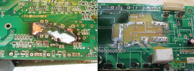
Extreme repair of PC board that was burned up after a capacitor failure. Hackaday photo.

Hackaday featured this guy’s extreme repair of his JBL subwoofer.  The power board had fried — it literally burned up in a catastrophic failure caused by leaking capacitors.  I looked at the details of his repair on his website and it was, quite frankly the most creative and professional repair I have ever seen.  Instead of buying a new board, or ditching the subwoofer and buying a new one, he actually cut out the damaged portion of the power supply board and used the amplifier service manual and Photoshop to create a new board to fit the hole.  His site is mostly pictures, the following quote is from the Hackaday article referencing his site:

[xsdb] had a real problem. His JBL L8400P 600 watt subwoofer went up in flames – literally. Four of the large capacitors on the board had bulged and leaked. The electrolyte then caused a short in the mains AC section of the board, resulting in a flare up. Thankfully the flames were contained to the amplifier board. [xsdb’s] house, possessions, and subwoofer enclosure were all safe. The amplifier board however, had seen better days. Most of us would have cut our losses and bought a new setup. Not [xsdb] he took on the most extreme PCB repair we’ve seen in a long time.

After removing the offending caps and a few other components, [xsdb] got a good look at the damage. the PCB was burned through. Charred PCB is conductive, so anything black had to be cut out. The result was a rather large hole in the middle of an otherwise serviceable board. [xsdb] had the service manual for the JBL sub. Amazingly, the manual included a board layout with traces. Some careful Photoshop work resulted in an image of the section of PCB to be repaired. [Xsdb] used this image to etch a small patch board.

The amplifier and patch were milled and sanded to match up nearly perfectly. Incredibly, all the traces aligned. [Xdsb] soldered the traces across the join with small sections of wire and solder wick. After soldering in some new high quality capacitors, the amplifier was back in action!

(published from Fort Wayne, Indiana)

Crosstown Traffic: Hackaday features Raspberry Pi-powered foxhunt transmitter — with or without an actual transmitter!

(my apologies about not posting in awhile.  I was on jury duty.  It was an emotionally draining case.  I’ll make up for it over the next few days.)

Hackaday ran an article yesterday that featured a hackaday.io project that Corey KM4EFP posted describing his Raspberry Pi powered Foxhunt transmitter.  What I found unique about this is that you can either feed the audio from a Pi output pin directly into a handheld transmitter, or actually transmit RF directly from the output pin (!) by adding a low-pass transmitter.  There is far more information about this project available on Corey’s GitHub page.  From the Hackaday.io project page:

My foxbox consists of a Raspberry Pi model B with Raspbian running pifox and is powered by a 6000mah usb power bank with a mausberrycircuits.com power switch and my gpio setup is laid out on an electro-resales gpio breakout pcb. All this is fitted inside a 30 caliber ammo can by use of non conductive foam padding. It starts transmitting automatically when the Pi is powered on and the transmit switch is flipped on. The transmission of my call sign and fox message and current time runs through gpio 4 and a lpf before reaching the antenna and also lighting an led indicating a transmission is in progress. No handheld is needed the Pi is the radio transmitter. You can also use audio out on the Pi to trigger vox on a handheld radio if your not comfortable building a low pass filter. Led and switches are also optional as well as automatic or manual transmissions and timing. Build your fox the way that suits you. There are many customizeable settings for pifox to fit your needs


We’ve seen directly driving an antenna from a GPIO pin before using PiFM.  I’m not sure I’d use it in any application where I would require frequency stability or any kind of a solid RF signal… but maybe the application of this is better than I originally thought.


(Published from DFW, Texas)

Crosstown Traffic: KB6NU Blog – Are knobs and buttons on the way out?

My friend Dan KB6NU has an interesting post on his blog about the evolving HMI (human-machine interface) between man (or woman) and radio:

In a recent column on EETimes, an old colleague of mine, Martin Rowe, says, “Knobs and buttons are slowly on their way out. Get used to it.” He’s referring to the controls on oscilloscopes, but if he were a ham, he might just as well be talking about amateur radio transceivers, too.

We already see this happening in amateur radio. FlexRadio, and a couple of other companies, already make transceivers with no front panel controls. You must use them in conjunction with a computer to use them.

KB6NU Blog: Are knobs and buttons toast?

Crosstown Traffic: Sparkfun comments on fake FTDI chips, more info comes out

As I predicted yesterday, Sparkfun has now commented on the counterfeit FTDI problem.  I had no doubt that their boards, like Adafruit’s, used genuine components… but you never know what can slip into the distribution stream from others:

As soon as we heard about it (from Twitter, of course), we immediately began assessing our product line for products which might be of concern. At the moment, we have about 30 individual products using the FT232 chip. We immediately crossed most of them off the list; our in-house assemblies are all produced using chips from reputable suppliers (like Mouser, Digikey, Future, etc.).


We have less visibility into assemblies that come pre-made to us, however, so we immediately set about testing them for vulnerability to this change. Testing is still ongoing, but our preliminary tests show that current stock is not affected. We already had the discussion with suppliers in the past regarding counterfeit chips (you may recall that we had a brush with this issue in the past), so we’re quite confident in the product we’re currently selling.

Read more

1 2 3