Category Archives: Interesting Ideas

Interesting Ideas: Using 75Ω RG-6 or RG-59 Coax in Ham Radio Applications

F type coaxial connector commonly used on 75Ω RG-6 and RG-59 coax. (Wikimedia photo)

I ran into this article from January tonight while cruising Facebook.  Michael Martens KB9VBR writes about the advantages and disadvantages of using cheap, easy-to-come-by RG-6 and RG-59 coaxial cable in amateur radio applications.  Of course, this type of cable, normally used for cable and satellite TV, closed circuit TV, and even some popular industrial automation networks (Allen-Bradley ControlNet and Modicon Remote IO) has a 75Ω impedance instead of the 50Ω impedance of coaxial cable that we normally use in radio, such as RG-58, RG-8, RG-8X, etc.  Is this a problem?  It can be, and it is more pronounced on VHF and UHF than it is on HF… which is kind of cool, because it’s more easily abated on UHF and VHF than it is at HF.  From Michael’s article:

The first method is to measure and cut your coax so the entire cable run can be measured in 1/2 wavelength multiples. For the two meter band, a half wave is approximately 38 inches. Keeping your cable length within these 1/2 wave multiples will present a near 50 Ohm match at the transmitter end of the line. But how does this work?

Say you where to take a length of 50 Ohm coax and put a 100 Ohm resister at the end. If you where to measure the impedance at the other end, what would it be? Not necessarily 50 Ohms. The reason is that coax offers a mix of resistive and reactive elements that change with the length of the coax. For example, using 1/4 wave length multiples of 75 Ohm coax will give you your 100 Ohm resister a 50 Ohm impedance at the transmitter end. Now if you were to substitute that resister with a 50 ohm antenna, using 1/2 wave multiples of 75 Ohm coax would give you a 50 Ohm impedance. Not too shabby.

This practice works well with VHF as the 1/2 waves are relatively short, so you don’t need to contend with a bunch of extra coax cable. But as you lower the frequency, those wavelengths increase, to the point were you’ve got up to 120 feet of extra cable on the 75 meter band.

Read more

Interesting Ideas: A counterpoise for your HT

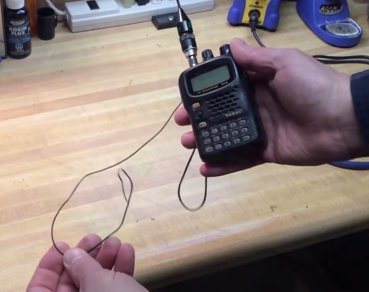
“Tiger Tail” counterpoise wire on a Yeasu VX-5 HT (hackaday.com photo)

Saw this idea earlier today on the Ham Radio Go Kits group on Facebook.  It’s called a “Tiger Tail” – something I’ve never heard of in my 26 years in ham radio.  Turns out it’s actually a thing, and not a bad idea, in theory – you attach a quarter-wavelength piece of wire to the ground side of your antenna connector on your handy-talky and just let it hang down — making your vertical HT antenna a full dipole. I’m not certain exactly how much this would improve things if you were actually holding the radio–the fact that you are holding the radio, especially if it’s made of metal, actually makes your body part of the antenna system and probably throws it off anyway.  God knows what happens to your antenna system if this thing is clipped to your belt.  But if you had the radio sitting on a wooden table, it might really help.

Read more

Interesting Ideas: Two-way Optoisolator made with two LEDs

When I was but a wee lad around the age of 10, I wandered into a Radio Shack with my father.   Of course, this is back when Radio Shack sold good electronics parts.  I wanted to know what they did.  My dad didn’t know.  Somehow I ended up with a copy of Getting Started in Electronics by Forrest Mims III.  The book was handwritten and the illustrations were hand drawn, and it was perfect for kids.  Or adults.  I still have a copy of this book, not the original one my dad bought me — I’ve since lent that out many years ago.  But I was able to pick up a copy from the third printing, still with the original green cover, and I’ll hold on to that one forever.  It cost something like three bucks at the time.  The book is still in print — you can get it from Amazon, Jameco, or from the W5YI group.

Homemade optoisolator made with two LEDs (drawing by Forrest Mims III)

I found this article at Jameco.com that Forrest wrote about using two LEDs as an optoisolator by mounting them facing each other and wrapping them in electrical tape.  I would probably use heat shrink tubing if I tried this.  This is an excellent application showing that an LED can also be used to detect light.  The example circuit uses the homemade optoisolator feeding a 4011 CMOS NAND gate as a driver for an output LED.

Read more

Interesting Ideas: The “Passive Repeater”

While futzing around the Internet yesterday, I came across an entry from “Joe’s Hobby Electronics” blog.  He had a problem with getting a cell phone signal in his home.  According to Joe, his “…village is in a bit of a dip and the population density just isn’t really high enough to warrant better coverage.”  According to his post, it is illegal to use cell phone repeaters in the UK (and while doing followup research, apparently most if not all of these repeaters are illegal in the US).

In an attempt to legally overcome his signal issue, Joe is in the process of setting up a “passive repeater” (he calls it a “Waveguide” but that term means something different in the US).  The theory is simple — you put up a directional antenna aimed at the cell tower and another omnidirectional antenna in your home.  Both antennas need to be tuned as close as possible to the target frequency and connected by the shortest possible length of the best possible feedline that you can get.  Antenna tuning and quality feedline is critical because this system is entirely passive — there are no amplifiers or powered components in the system at all.  Here’s how it works:
Read more