Tag Archives: Hackaday

Crosstown Traffic: 3D Printing-Want a circuit with that?

As most technical-oriented people are, I am fascinated with 3D Printing.  They have a PolyPrinter 3D printer over at Tanner Electronics (video here) — they sell them, and they will also print out your file on their printer for a few bucks.  I could watch that thing print for hours.  Even though the costs are coming down, I can’t justify purchasing one yet.  But they have one hell of a cool factor.

Yesterday, Hackaday featured two special printers that were demonstrated at the Consumer Electronics Show.  The Voltera is cool enough — it prints a circuit onto a substrate using silver conductive ink.  It can even make a second layer on top of the first by printing an insulating layer and then a second conductive layer.  This sounds great for making circuit boards in a hurry.  What could be better than that?

Oh, wait.  How about the Voxel8?  It also prints circuits.  And, it’s also a 3D printer.  And it does both at the same time.  In 3D.

The Voxel8 marries the idea of a 3D printer with a silver conductive ink dispenser. You start by modeling your entire design, hardware and electronics, all in one. The printer will then begin the 3D print, pausing when necessary for you to add electronics and mechanicals. With the parts — and their pins — in place it lays out the conductive ink to connect the components and then continues with the 3D printing to finish the object.

Now that’s cool!


(Published from DFW, Texas)

Crosstown Traffic: Hackaday “Retrotachtacular” – 1978 Bell Systems video about Mobile Telephone Service

This week’s “Retrotachtacular” on Hackaday features a 1978 Bell System video about the Advanced Mobile Phone Service (AMPS):

This gem from the AT&T Archive does a good job of explaining the first-generation cellular technology that AT&T called Advanced Mobile Phone Service (AMPS). The hexagon-cellular network design was first conceived at Bell Labs in 1947. After a couple of decades spent pestering the FCC, AT&T was awarded the 850MHz band in the late 1970s. It was this decision coupled with the decades worth of Bell System technical improvements that gave cellular technology the bandwidth and power to really come into its own.

AT&T’s primary goals for the AMPS network were threefold: to provide more service to more people, to improve service quality, and to lower the cost to subscribers. Early mobile network design gave us the Mobile Service Area, or MSA. Each high-elevation transmitter could serve a 20-mile radius of subscribers, a range which constituted one MSA. In the mid-1940s, only 21 channels could be used in the 35MHz and 150MHz band allocations. The 450MHz band was introduced in 1952, provided another 12 channels.

The FCC’s allocation opened a whopping 666 channels in the neighborhood of 850MHz. Bell Labs’ hexagonal innovation sub-divided the MSAs into cells, each with a radius of up to ten miles.

This is a cool video.  Click through to Hackaday to watch it and read more.


(Published from DFW, Texas)

Crosstown traffic: Hackaday features my “FatFingerer” on their front page

Whether this was the result of people actually liking my project or just some random randomizer picking featured projects, I saw this on the Hackaday front page this evening (and no, I wasn’t logged into my account on Hackaday, and yes, I checked this from multiple browsers to make sure this wasn’t a cookie thing…) :

Screengrab from Hackaday, 11/14/2014 7:25 PM

Screengrab from Hackaday, 11/14/2014 7:25 PM

I detailed my FatFingerer to my friends on Facebook a number of months ago, I do plan on adding a detailed writeup to my blog in the near future… I use the FatFingerer every day at work when using AutoCAD and PLC applications, the heart of it is an Arduino Leonardo programmed to emulate common keystrokes.  And yes, if you’re interested in more detail right now, here is my Hackaday.io project page for the FatFingerer.


(published from Fort Wayne, Indiana)

Crosstown traffic: The most extreme PC board repair I’ve ever seen

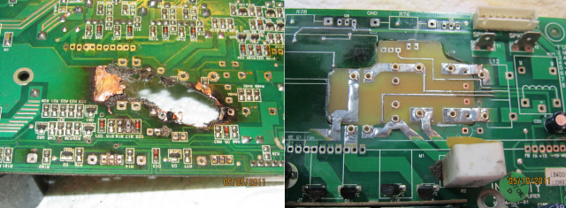
Extreme repair of PC board that was burned up after a capacitor failure. Hackaday photo.

Hackaday featured this guy’s extreme repair of his JBL subwoofer.  The power board had fried — it literally burned up in a catastrophic failure caused by leaking capacitors.  I looked at the details of his repair on his website and it was, quite frankly the most creative and professional repair I have ever seen.  Instead of buying a new board, or ditching the subwoofer and buying a new one, he actually cut out the damaged portion of the power supply board and used the amplifier service manual and Photoshop to create a new board to fit the hole.  His site is mostly pictures, the following quote is from the Hackaday article referencing his site:

[xsdb] had a real problem. His JBL L8400P 600 watt subwoofer went up in flames – literally. Four of the large capacitors on the board had bulged and leaked. The electrolyte then caused a short in the mains AC section of the board, resulting in a flare up. Thankfully the flames were contained to the amplifier board. [xsdb’s] house, possessions, and subwoofer enclosure were all safe. The amplifier board however, had seen better days. Most of us would have cut our losses and bought a new setup. Not [xsdb] he took on the most extreme PCB repair we’ve seen in a long time.

After removing the offending caps and a few other components, [xsdb] got a good look at the damage. the PCB was burned through. Charred PCB is conductive, so anything black had to be cut out. The result was a rather large hole in the middle of an otherwise serviceable board. [xsdb] had the service manual for the JBL sub. Amazingly, the manual included a board layout with traces. Some careful Photoshop work resulted in an image of the section of PCB to be repaired. [Xsdb] used this image to etch a small patch board.

The amplifier and patch were milled and sanded to match up nearly perfectly. Incredibly, all the traces aligned. [Xdsb] soldered the traces across the join with small sections of wire and solder wick. After soldering in some new high quality capacitors, the amplifier was back in action!

(published from Fort Wayne, Indiana)

Crosstown Traffic: Hackaday features Raspberry Pi-powered foxhunt transmitter — with or without an actual transmitter!

(my apologies about not posting in awhile.  I was on jury duty.  It was an emotionally draining case.  I’ll make up for it over the next few days.)

Hackaday ran an article yesterday that featured a hackaday.io project that Corey KM4EFP posted describing his Raspberry Pi powered Foxhunt transmitter.  What I found unique about this is that you can either feed the audio from a Pi output pin directly into a handheld transmitter, or actually transmit RF directly from the output pin (!) by adding a low-pass transmitter.  There is far more information about this project available on Corey’s GitHub page.  From the Hackaday.io project page:

My foxbox consists of a Raspberry Pi model B with Raspbian running pifox and is powered by a 6000mah usb power bank with a mausberrycircuits.com power switch and my gpio setup is laid out on an electro-resales gpio breakout pcb. All this is fitted inside a 30 caliber ammo can by use of non conductive foam padding. It starts transmitting automatically when the Pi is powered on and the transmit switch is flipped on. The transmission of my call sign and fox message and current time runs through gpio 4 and a lpf before reaching the antenna and also lighting an led indicating a transmission is in progress. No handheld is needed the Pi is the radio transmitter. You can also use audio out on the Pi to trigger vox on a handheld radio if your not comfortable building a low pass filter. Led and switches are also optional as well as automatic or manual transmissions and timing. Build your fox the way that suits you. There are many customizeable settings for pifox to fit your needs


We’ve seen directly driving an antenna from a GPIO pin before using PiFM.  I’m not sure I’d use it in any application where I would require frequency stability or any kind of a solid RF signal… but maybe the application of this is better than I originally thought.


(Published from DFW, Texas)

Crosstown Traffic: Hackaday and Adafruit Report Latest Windows Update Kills Fake FTDI Chips

This could be bad.  Apparently there are lots of counterfeit FTDI232 chips out there–these are the chips that convert your USB to RS-232 serial or TTL serial.

The folks over at Hackaday and Adafruit are reporting that the latest Windows update includes a driver that nukes fake FTDI chips.  It doesn’t just keep Windows from using them.  It bricks them, rendering them unusable.  Ever.

I have a few USB to serial devices, both board level and consumer devices.  Most of them came from reputable sources (Modern Device, Arduino, Picaxe, Tripp-Lite, etc) but I have a few Chinese imports from eBay that I expect to fail the next time I plug them in.  Adafruit reports that it

… requires it suppliers to only use genuine FTDI chips. However, no matter what it’s always possible counterfeit chips could be used when you purchase products from anyone, anywhere. We’re double and triple checking all our products and suppliers as an added precaution.

I’m assuming SparkFun will also issue a note addressing their products as well.

(as an aside, the Tripp-Lite Keyspan USB Adapter is the best USB-Serial adapter I have ever encountered.  It has worked on industrial Allen-Bradley equipment, my mobile Kenwood radio, and everything else I have plugged it into.  If you’re sick of the USB-Serial adapters that only sometimes work, shell out a few more dollars and buy one of these.)


(published from DFW, Texas)

Crosstown Traffic: Hackaday Hacklet #19 – Ham Radio – SDR, Foxhunt Attenuator, and Ethernet to Radio Adapter

The folks over at Hackaday featured Ham Radio in their latest edition of the Hacklet, their weekly newsletter covering projects posted on their hackaday.io site.  The first project, titled “RTL-SDR With Upconverter and Case” features the use of an upconverter to enable the SDR dongle to pick up HF.  Pretty handy, considering the stock RTL-SDR has a low limit of about 24 MHz. I just picked up one of these SDR dongles, so I’ll have to look into getting the upconverter.

Like fox hunting?  Attach the “Ham Radio Fox Hunt Attenuator” to your HT to reduce the sensitivity of your portable as you close in on that tiny low-powered transmitter.  This one uses a couple of 1K potentiometers abd boasts a “…first of its kind variable attenautor vs multiple switches. 1-20 and 21-60 db. with a 3rd option of bypass/straight through.”  The ones I’ve used in the past have a bank of switches that switch resistors in an out, so their might be some advantage to the variable unit. Read more